Assessing Elevation Changes with Precision Tools

Assessing Elevation Changes with Precision Tools

The claims process for foundation repair services: steps homeowners should take to ensure a smooth and successful outcome.

Here's an article outline for 'Assessing Elevation Changes with Precision Tools' in the context of 'Residential Foundation Repair Services':


In the realm of residential foundation repair services, assessing elevation changes with precision tools is a critical aspect of ensuring a home's structural integrity and safety. Ignoring minor foundation issues can lead to severe structural failure residential foundation repair service wall. Over time, foundations can settle, heave, or shift due to various factors such as soil expansion, erosion, or inadequate compaction. These movements can lead to uneven floors, cracked walls, and other structural issues that necessitate professional repair.

Precision tools play a pivotal role in accurately measuring and evaluating these elevation changes. One of the most commonly used tools is the leveling instrument, which can range from simple spirit levels to sophisticated digital levels. These devices help technicians determine the relative elevation of different points on the foundation, identifying areas that have settled or heaved. By establishing a benchmark or reference point, technicians can compare multiple readings to understand the extent and pattern of movement.

Another essential tool is the total station, a high-precision surveying instrument that combines an electronic distance measurement device with an electronic transit theodolite. This tool allows for precise measurement of angles and distances, providing a comprehensive map of elevation changes across the foundation. The data collected can be used to create detailed reports and 3D models, offering a visual representation of the foundation's condition.

Additionally, ground-penetrating radar (GPR) is increasingly being used in foundation repair services. GPR uses radar pulses to image the subsurface, identifying voids, cracks, and other anomalies that may not be visible from the surface. This non-invasive method provides valuable insights into the underlying causes of elevation changes, helping technicians develop more targeted repair strategies.

The use of these precision tools not only ensures accurate diagnoses but also facilitates effective planning and execution of repair work. For instance, by pinpointing the exact locations of settlement or heaving, technicians can implement solutions such as underpinning, slabjacking, or soil stabilization with greater precision. This targeted approach minimizes disruption to the home and reduces the overall cost of repairs.

Moreover, regular monitoring with precision tools can help in the early detection of potential foundation issues. Homeowners can schedule periodic inspections to track any subtle changes in elevation over time. This proactive approach allows for timely interventions before minor issues escalate into major structural problems.

In conclusion, assessing elevation changes with precision tools is indispensable in residential foundation repair services. By leveraging advanced instruments like levels, total stations, and ground-penetrating radar, professionals can accurately diagnose foundation issues and implement effective repair strategies. This ensures the longevity and safety of residential structures, providing homeowners with peace of mind and a secure living environment.

Brief overview of common causes of foundation issues related to elevation changes, such as soil settlement, heaving, or erosion.


Elevation changes around a building's foundation can lead to several issues that compromise its structural integrity. Understanding the common causes of these problems is essential for assessing and addressing them effectively with precision tools.

One of the primary causes of foundation issues related to elevation changes is soil settlement. This occurs when the soil beneath a foundation compresses over time, leading to a drop in elevation. Settlement can be uniform or differential; the latter is more problematic as it causes the foundation to move unevenly, leading to cracks and other structural damages. Precision tools like leveling instruments and laser scanners can help monitor and measure these changes over time, providing crucial data for remediation strategies.

Heaving, on the other hand, is the upward movement of a foundation due to swelling soils. This typically occurs in clay-rich soils that expand when they absorb water and shrink when they dry out. Heaving can cause the foundation to lift and crack, damaging the structure above. Using tools like inclinometers and tilt sensors can help detect and measure heaving, allowing for early intervention and prevention of severe damage.

Erosion is another significant cause of foundation issues related to elevation changes. Water runoff, improper drainage, or landscaping changes can lead to soil erosion, washing away the soil supporting the foundation. This loss of support can cause the foundation to settle or shift unevenly, leading to structural problems. Precision tools like ground-penetrating radar (GPR) and drone surveying can help identify areas prone to erosion and monitor changes in soil levels around the foundation.

Other factors contributing to elevation changes include poor compaction during construction, changes in moisture content due to plumbing leaks or weather variations, and even natural phenomena like earthquakes. Each of these issues can be identified and evaluated using various precision tools tailored to the specific problem. By regularly assessing elevation changes with these tools, homeowners and professionals can detect foundation issues early, implement corrective measures, and prevent further damage to the structure.

Explanation of various precision tools used to measure elevation changes, including levels (spirit/laser), total stations/GPS systems used by professionals). Describe how each tool works briefly (no subheadings). For example laser level utilizes light and receiver for accuracy.


Assessing elevation changes accurately is crucial in various fields such as surveying civil engineering construction forests agriculture mining geology archeology architecture urban planning transportation infrastructure development etcetera Hence precision instruments become indispensable tools In understanding how professionals measure these elevation changes various tools stand out namely levels both spirit/dumpy/auto levels/ laser levels total stations Global Positioning System GPS Here' s brief overview how each tool operates starting wit levels Spirit level also known dumpy level auto level consists telescope tube fitted precise bubble vials cross hair plate micrometer screw staff Its basic working principle involves sighting through telescope towards graduated staff held vertical position ground Bubble vials ensure horizontality telescope enabling user read elevation accurately Laser level works differently utilizing laser light beam projected onto surface where receiver detect device reads elevation based where laser hits Total station combines electronic transit EDM electronic distance measurement angle encoder microprocessor data collector all integrated unit It shoot laser beam towards reflector positioned point interest measures angles distances simultaneously compute coordinates data collected eventually used plot elevations GPS receivers determine positioning using signals transmitted satellites orbit Process called trilateration GPS receiver picks up signals minimum four satellites computes position including elevation based differences timing signals High precision GPS system used geodetic surveying incorporate real time kinematic RTK corrections further enhancing accurate results In practice professionals may choose tool depending specific requirements project terrain conditions accuracy desired accessibility cost effectiveness Thus mastery these precision tools paramount ensuring reliable data collection ultimately leading informed decision making shaping our environment

Step-by-step guide on how to use these tools effectively, emphasizing safety and accuracy from setup through calibration to measurement collection.


Assessing elevation changes with precision tools is a crucial task in various fields such as surveying, construction, and environmental monitoring. To ensure accuracy and safety, it's essential to follow a step-by-step guide when using these tools effectively throughout setup calibration measurement collection . Here are key points focusing mainly upon Total Stations Leica Disto laser measuring tools :

Setup:

Begin by selecting a suitable location for your instrument. For a Total Station, choose a spot that provides a clear line of sight to your targets minimizes obstructions ensures stability . Set your tool securely using tripod ensure its stability . For Leica Disto Ensure proper handling carry case avoid exposure moisture dust . Proper setup guaranteessafety accurate measurements ensuring reliable results right start . Once positioned level instrument carefully using bubble level .

Calibration:

Before collecting measurements , calibrate tool ensures accuracy . For Total Station follow manufacturer's guidelines usually involves sighting known points checking instrument's compensator . Leica Disto devices can be calibrated using reference distances provided by manufacturer . Regular calibration critical maintaining tool's precision avoiding errors . Follow procedure meticulously avoid rushing process .

Measurement Collection:

With setup calibration complete, proceed collecting measurements . Total Station requires careful aiming at targets using telescope precise focusing . Record horizontal vertical angles distances accurately . Use prism poles reflectors enhance accuracy when measuring long distances . Leica Disto measure distances simply aiming laser point at target pressing button . Ensure stable position laser point clearly visible target surface obtaining consistent readings . Double-check measurements minimize human error record data systematically maintain organized records . Always prioritize safety especially when measuring hazardous areas steep terrains . Use safety gear protective clothing necessary wear reflective vests increase visibility . Avoid working near power lines hazardous materials prevent accidents . Regularly inspect tools for damage malfunctions ensure optimal performance safety . Keep tools clean store properly prolong lifespan maintain accuracy .

Post-Measurement:

After collecting data transfer measurements digital format analyze using appropriate software . Verify data integrity check consistency with known benchmarks . Document process findings clearly concisely report accurate results . Maintain a log all activities including setup calibration measurements analysis future reference troubleshooting purposes . Ensure proper care maintenance tools following manufacturer's recommendations extending their lifespan .

In conclusion assessing elevation changes precision tools requires meticulous attention detail adherence safety protocols ensuring accurate reliable results throughout setup calibration measurement collection process understanding importance regular maintenance careful handling prolong tool's life accuracy ensuring successful outcomes every project undertaken .

Interpretation of results: Understanding what the measurements indicate about the foundation's condition and potential issues (such as differential settlement/cracking). Mention industry standards for acceptable elevation differences if applicable .


Assessing elevation changes with precision tools is a critical aspect of monitoring the health and stability of foundations. This process involves taking accurate measurements over time to detect any signs of movement, settlement, or other potential issues. The interpretation of these results is where the real value lies, as it helps professionals understand what the measurements indicate about the foundation's condition.

When assessing elevation changes, one of the key concerns is differential settlement, which can lead to cracking and other structural issues. Differential settlement occurs when different parts of a foundation settle at different rates, causing uneven stress distribution. Precision tools such as levels, total stations, and laser scanners can detect even the slightest changes in elevation, providing a detailed picture of what's happening beneath the surface.

Industry standards play a significant role in determining what constitutes acceptable elevation differences. For instance, the American Concrete Institute (ACI) and the International Building Code (IBC) provide guidelines for tolerable settlement levels based on factors such as soil conditions/type(either expansive or collapsible), load bearing capacities etcetera . Generally acceptable differential settlement ranges between 1 inch per 30 feet (25 mm per 9 meters) to 1 inch per 15 feet (25 mm per 4 meter). However these values might vary depending upon building design/structure type(either framed or rigid) also . These standards help engineers and surveyors evaluate whether the measured elevation differences fall within acceptable limits or indicate potential problems that need addressing(such as soil stabilization).

Interpreting these results involves more than just comparing numbers to standards; it requires a thorough understanding of the building's design, the surrounding soil conditions, and any external factors that could influence settlement (eg . Groundwater changes). For example , if measurements show that one corner of a building has settled more than another over several months during rainy season , it might indicate issues such as water erosion or soil expansion rather than structural failure . Therefore , Interpretation plays crucial role here . It helps professionals make informed decisions about maintenance , repairs , or even structural reinforcements . With advances continually made within technology tools used like drone mapping /LIDAR/GPR(ground penetrating radar) etcetera . Professionals can gather even more comprehensive data , leading to even precise interpretations . However human expertise remains crucial here too . Combining technical data analysis alongwith experienced judgement ensures accurate decision making ensuring long-term foundation stability . Therefore understanding what measurements indicate about foundation's condition remains essential step towards ensuring overall safety/durability of any structure .

How professional foundation repair services use this information to recommend specific repairs, such as house leveling, underpinning, or soil stabilization etc.


Professional foundation repair services utilize precise elevation assessment tools to gather critical information about a home's foundation, enabling them to recommend specific and effective repairs. These tools, which can include laser levels, digital altimeters, and remote sensing technologies like LiDAR, help experts detect even the slightest changes in elevation, indicative of foundation issues such as settling, sinking, or upheaval.

When a foundation repair specialist first visits a site, they establish a reference point, typically a stable structure or fixture unaffected by the foundation shift. Using their precision tools, they measure and compare elevations at various points around the foundation, creating a detailed map of the current foundation landscape. By comparing these measurements to the original or expected elevations, they can identify problem areas that require attention.

If a section of the foundation has sunk or settled, experts may recommend house leveling. This process involves lifting the affected area using jacks or other specialized equipment until it reaches its original elevation. Once leveled, they may suggest additional support methods like piers or pilings to maintain the corrected elevation.

In cases where the foundation has shifted due to soil instability or poor initial construction, underpinning might be recommended. Underpinning involves extending the foundation depth-wise or range-wise to transfer the building's weight to more stable soil layers. This can be achieved through methods like push piers or helical piers, which are driven deep into the ground to provide additional support.

Soil stabilization is another common recommendation stemming from elevation change assessments. If the soil beneath the foundation is weak or expansive (swelling with water and shrinking upon drying), it can cause recurring foundation issues. Soil stabilization techniques such as chemical grouting or soil modification can strengthen the soil and mitigate future movement.

In some instances, a combination of these repair methods may be suggested based on the elevation data and other diagnostic information. Professional foundation repair services rely heavily upon precise elevational assessments throughout planning & execution phases - rechecking measurements post-repair ensures work quality & foundational integrity moving forward.

Importance of regular monitoring and assessment of elevation changes by homeowners or professionals to prevent serious foundation problems and maintain residential property value (could mention seasons/weather conditions impact).


Regular monitoring and assessment of elevation changes in and around a home are crucial for preventing serious foundation problems and maintaining residential property value. This vigilance is not just a task for professionals; homeowners also play a vital role in this process. By keeping an eye on elevation shifts, homeowners can identify potential issues early, before they become costly repairs.

Foundation issues often stem from changes in the soil beneath a home. These changes can occur due to various factors, with seasons and weather conditions playing significant roles. For instance, during rainy seasons, soil can expand as it absorbs water, leading to upward movements known as heaving-while during dry periods; soil contraction causes settling which leads homes foundation sink unevenly causing cracks both interior & exterior walls plus jammed doors & windows amongst other signs.

To track these elevation changes precisely; advanced tools such altimeters digital levels GPS systems or remotely sensed InSAR data offer accurate readings helping pinpoint problematic areas efficiently allowing timely intervention avoiding severe damage later stages.. However precision tools aren'ts always readily accessible hence simple methods e .g using string levels bubble levels alongside visual inspection cracks measurement periodically helps catching initial warning signs..

Professionals like surveyors or foundation specialists should be consulted periodically ideally annually unless noticeable changes happen sooner; they bring expertise coupled modern equipment giving comprehensive analysis foundation status providing recommendations necessary repairs prevention measures respectively ensuring property structural integrity maintained ultimately preserving its market value.. Additionally keeping records monitoring observations enables tracking patterns correlate findings weather events facilitating proactive approach managing potential threats posed changing elevations overall ensure safety longevity investment i.e.,your home.. In essence collaborative effort between homeowner specialist complemented regular checks precise tools proves effective strategy mitigating risks associated elevations fluctuations safeguarding both foundation health property value alike..


Facebook about us:

Residential Foundation Repair Services

Strong Foundations, Strong Homes


(Learn how and when to remove this message)

Radon mitigation is any process used to reduce radon gas concentrations in the breathing zones of occupied buildings, or radon from water supplies. Radon is a significant contributor to environmental radioactivity and indoor air pollution. Exposure to radon can cause serious health problems such as lung cancer.[1]

Mitigation of radon in the air by active soil depressurization is most effective. Concrete slabs, sub-floors, and/or crawlspaces are sealed, an air pathway is then created to exhaust radon above the roof-line, and a radon mitigation fan is installed to run permanently. In particularly troublesome dwellings, air exchangers can be used to reduce indoor radon concentrations. Treatment systems using aeration or activated charcoal are available to remove radon from domestic water supplies. There is no proven link between radon in water and gastrointestinal cancers; however, extremely high radon concentrations in water can be aerosolized by faucets and shower heads and contribute to high indoor radon levels in the air.

Testing

[edit]
A typical radon test kit
Fluctuation of ambient air radon concentration over one week, measured in a laboratory

The first step in mitigation is testing. No level of radiation is considered completely safe, but as it cannot be eliminated, governments around the world have set various action levels to provide guidance on when radon concentrations should be reduced. The World Health Organization's International Radon Project has recommended an action level of 100 Bq/m3 (2.7 pCi/L) for radon in the air.[2] Radon in the air is considered to be a larger health threat than radon in domestic water. The US Environmental Protection Agency recommendation is to not test for radon in water unless a radon in air test shows concentrations above the action level. However, in some U.S. states such as Maine where radon levels are higher than the national average, it is recommend that all well water should be tested for radon. The U.S. government has not set an action level for radon in water.

Air-radon levels fluctuate naturally on a daily and seasonal basis. A short term test (90 days or less) might not be an accurate assessment of a home's average radon level, but is recommended for initial testing to quickly determine unhealthy conditions. Transient weather such as wind and changes in barometric pressure can affect short-term concentrations as well as ventilation, such as open windows and the operation of exhaust fans.

Testing for radon in the air is accomplished using passive or active devices placed in the building. Some devices are promptly sent to a laboratory for analysis, others calculate the results on-site including digital Radon detectors. Radon-in-water testing requires a water sample being sent to a laboratory.

Retesting is recommended in several situations, for example, before spending money on the installation of a mitigation system. Test results which exceed accuracy tolerances also require re-testing. When a mitigation system installation is warranted, a retest after the system is functional is advised to be sure the system is effectively reducing the radon concentration below the action level, and after any mitigation system repairs such as replacing a fan unit. The US EPA recommends retesting homes with radon problems every two years to ensure proper system function. Due to the vast fluctuation in indoor radon levels, the EPA recommends all homes be tested at least once every five years.[3]

Testing in the United States

[edit]
Radon map of the United States

ASTM E-2121 is a US standard for reducing airborne radon in homes as far as practicable below the action level of 4 picocuries per liter (pCi/L) (148 Bq/m3).[4][5] Some states recommend achieving 2.0 pCi/L or less.

Radon test kits are commercially available[6] and can be used by homeowners and tenants and in limited cases by landlords, except when a property is for sale.

Commercially available test kits include a passive collector that the user places in the lowest livable floor of the house for 2 to 7 days. The user then sends the collector to a laboratory for analysis. Long-term kits, taking collections from 91 days to one year, are also available. Open land test kits can test radon emissions from the land before construction begins, but are not recommended by the EPA because they do not accurately predict the final indoor radon level. The EPA and the National Environmental Health Association have identified 15 types of radon test devices.[7] A Lucas cell is one type of device.

Retesting is specifically recommended in several situations. Measurements between 4 and 10 pCi/L (148 and 370 Bq/m3) warrant a follow-up short-term or long-term radon test before mitigation. Measurements over 10 pCi/L (370 Bq/m3) warrant only another short-term test (not a long-term test) so that abatement measures are not unduly delayed.

Progress has been made regarding radon in the home. A total of 37 states have now[when?] passed legislation requiring home-sellers to disclose known radon levels before completing the transaction (although only a handful have introduced criminal penalties for misrepresentation).[8] And over half the legislatures have written radon into their state's building code.[9] Purchasers of real estate may delay or decline a purchase if the seller has not successfully abated radon to less than 4 pCi/L.

The accuracy of the residential radon test depends upon whether closed house conditions are maintained. Thus the occupants will be instructed not to open windows, etc., for ventilation during the pendency of test, usually two days or more. However, the occupants, if the present owners, will be motivated to pass the test and insure the sale, so they might be tempted to open a window to get a lower radon score. Moreover, there may be children or immature teens or young adults in the house who will open a window for ventilation notwithstanding instructions not to do so, particularly in uncomfortably hot weather. Accordingly, whether the potential purchaser should trust the result of such a test is problematic.

Management of radon service provider certification has evolved since being introduced by the EPA in 1986. In the 1990s this service was "privatized" and the National Environmental Health Association (NEHA) helped transition the voluntary National Radon Proficiency Program (NRPP) to be administered by private firms. As of 2012, the NRPP is administered by the American Association of Radon Scientists and Technologists (AARST).[10]

Some states, such as Maine, require landlords to test their rental properties and turn the results in to the state. In limited cases the landlord or tenants may do the testing themselves. The rules in each state vary. In many cases there are private contractors that will inspect hired by the city.

Testing in Canada

[edit]

Health Canada recommends regular annual testing, either by hiring a qualified tester or by using a home-testing kit that should be checked quarterly.[11]

Canadian Government, in conjunction with the territories and provinces, developed the guideline[12] to indicate when remedial action should be taken was originally set at 800 Bq/m3 (becquerels per cubic meter) and since reduced to 200 Bq/m3. This new guideline was approved by the Federal Provincial Territorial Radiation Protection Committee in October 2006.[13]

Testing in the UK

[edit]

Radon testing in the UK is managed by UKradon and the UKHSA.[14]

Testing in Norway

[edit]

The Norwegian Radiation and Nuclear Safety Authority (DSA) developed the protocol[15] for radon measurements in residential dwellings[16] with respect to rental accommodation, which is governed by The Radiation Protection Regulations.[17]

Methods of radon gas mitigation

[edit]
Part of a radon mitigation system including the fan and vent pipe is visible near the gutter downspout.

Because high levels of radon have been found in every state of the United States,[18] testing for radon and installing radon mitigation systems has become a specialized industry since the 1980s. Many states have implemented programs that affect home buying and awareness in the real estate community; however, radon testing and mitigation systems are not generally mandatory unless specified by the local jurisdiction.[19]

Anticipated high radon levels can be mitigated during building design and construction by a combination of ensuring a perfectly sealed foundation, allowing sufficient passive dispersal of under-slab gas around rather than through the building, and proper building ventilation. In many instances, such approaches may achieve a sufficient reduction of radon levels compared to other buildings where such approaches were not taken. However, quality of implementation is crucial and testing after construction is necessary. For instance, even a small gap in the sealing of the slab may be sufficient for excessive quantities of radon to enter, given pressure differentials.

Where such approaches were not taken during construction or have proven insufficiently effective, remediation is needed. According to the EPA's "A Citizen's Guide to Radon",[20] the method to reduce radon "primarily used is a vent pipe system and fan, which pulls radon from beneath the house and vents it to the outside", which is also called sub-slab depressurization, soil suction, or active soil depressurization (ASD). Generally indoor radon can be mitigated by sub-slab depressurization and exhausting such radon-laden air to the outdoors, away from windows and other building openings.[21] "EPA generally recommends methods which prevent the entry of radon. Soil suction, for example, prevents radon from entering your home by drawing the radon from below the home and venting it through a pipe, or pipes, to the air above the home where it is quickly diluted" and "EPA does not recommend the use of sealing alone to reduce radon because, by itself, sealing has not been shown to lower radon levels significantly or consistently" according to the EPA's "Consumer's Guide to Radon Reduction: How to Fix Your Home".[22] Ventilation systems can utilize a heat exchanger or energy recovery ventilator to recover part of the energy otherwise lost in the process of exchanging air with the outside. For crawlspaces, the EPA states,[22] "An effective method to reduce radon levels in crawlspace homes involves covering the earth floor with a high-density plastic sheet. A vent pipe and fan are used to draw the radon from under the sheet and vent it to the outdoors. This form of soil suction is called submembrane suction, and when properly applied is the most effective way to reduce radon levels in crawlspace homes."

High radon levels in a Minnesota (USA) basement with a passive under slab vent pipe system can be seen in the left half of the graph. After installation of a radon fan (ASD), a permanent reduction in radon levels to approximately 0.6 pCi/L can be seen in the right half of the graph.
  • The most common approach is active soil depressurization (ASD). Experience has shown that ASD is applicable to most buildings since radon usually enters from the soil and rock underneath and mechanical ventilation is used when the indoor radon is emitted from the building materials. A less common approach works efficiently by reducing air pressures within cavities of exterior and demising walls where radon emitting from building materials, most often concrete blocks, collects.
  • Above slab air pressure differential barrier technology (ASAPDB) requires that the interior pressure envelope, most often drywall, as well as all ductwork for air conditioning systems, be made as airtight as possible. A small blower, often no more than 15 cubic feet per minute (0.7 L/s) may then extract the radon-laden air from these cavities and exhaust it to the out of doors. With well-sealed HVAC ducts, very small negative pressures, perhaps as little as 0.5 pascal (0.00007 psi), will prevent the entry of highly radon-laden wall cavity air from entering into the breathing zone. Such ASAPDB technology is often the best radon mitigation choice for high-rise condominiums as it does not increase indoor humidity loads in hot humid climates, and it can also work well to prevent mold growth in exterior walls in heating climates.
  • In hot, humid climates, heat recovery ventilators (HRV) as well as energy recovery ventilators (ERV) have a record of increasing indoor relative humidity and dehumidification demands on air conditioning systems. Mold problems can occur in homes that have been radon mitigated with HRV and ERV installations in hot, humid climates.[citation needed] HRVs and ERVs have an excellent record in cold dry climates.
  • A recent technology is based on building science. It includes a variable rate mechanical ventilation system that prevents indoor relative humidity from rising above a preset level such as 50% which is currently suggested by the US Environmental Protection Agency and others as an upper limit for the prevention of mold. It has proven to be especially effective in hot, humid climates. It controls the air delivery rate so that the air conditioner is never overloaded with more moisture than it can effectively remove from the indoor air.
    • It is generally assumed that air conditioner operation will remove excess moisture from the air in the breathing zone, but it is important to note that just because the air conditioner cools does not mean that it is also dehumidfying. If Δt is 14 degrees or less, it may not dehumidify at all even though it is cooling.
    • Factors that are likely to aggravate indoor humidity problems from mechanical ventilation–based radon installations are as follows and an expert radon mitigator/building scientist will check for and correct any and all of the following when he or she performs radon mitigation procedures:
      • Air conditioner duct leaks located outside the breathing zone, such as in the attic.
      • Excessive exhaust fan operation
      • Oversize or over-capacity air conditioners
      • AC air handler fans that do not stop running when the air conditioner compressor stops running.
      • Delta tt), which is the amount that the air is cooled as it is passed through the air conditioner's cooling coils. A good Δt performance figure for home air conditioners is about 20 °F (11 °C). In comparison, automobile air conditioners deliver Δt performance of 32 to 38 °F (18 to 21 °C). A Δt of 14 °F (8 °C) will dehumidify poorly if at all.

In South Florida, most radon mitigation is performed by use of fixed rate mechanical ventilation. Radon mitigation training in Florida does not include problems associated with mechanical ventilation systems, such as high indoor humidity, mold, moldy odors, property damage or health consequences of human occupation in high humidity of moldy environments[citation needed]. As a result, most Florida radon mitigators are unaware of and do not incorporate existing building science moisture management technology into mechanical ventilation radon installations. Home inspectors may not necessarily be aware of the mold risks associated with radon mitigation by mechanical ventilation.

The average cost for an ASD radon mitigation system in Minnesota is $1500.[23] These costs are very dependent on the type of home and age of construction.[24]

Methods of radon-in-water mitigation

[edit]

Radon removal from water supplies may be at a treatment plant, point of entry, or point of use. Public water supplies in the United States were required to treat for radionuclides beginning in 2003 but private wells are not regulated by the federal government as of 2014. The radon can be captured by granular activated charcoal (GAR) or released into the air through aeration of the water. Radon will naturally dissipate from water over a period of days, but the quantity of storage needed to treat the water in this manner makes home systems of this type impracticably large.[25]

Activated carbon systems capture radon from the water. The amount of radiation accumulates over time and the filter material may reach the level of requiring disposal as a radioactive waste. However, in the United States there are no regulations concerning radiation levels and disposal of radon treatment waste as of 2014.

Aeration systems move the radon from the water to the air. Radon gas discharged into the air is the release of a pollutant, and may become regulated in the United States.

References

[edit]
  1. ^ Nunnally, Diamond (2022-03-30). "Dangerous radon gas dangers and detection tips". WBMA. Retrieved 2022-04-10.
  2. ^ WHO Handbook on Indoor Radon: A Public Health Perspective. World Health Organization. 2009.
  3. ^ US EPA, OAR (2013-08-27). "Radon". www.epa.gov. Retrieved 2023-02-04.
  4. ^ "Recommended Residential Radon Mitigation Standard of Practice". United States Environmental Protection Agency. Archived from the original on 2008-01-16. Retrieved 2008-02-02.
  5. ^ "ASTM E2121-03 Standard Practice for Installing Radon Mitigation Systems in Existing Low-Rise Residential Buildings". ASTM International. Retrieved 2008-02-02.
  6. ^ "Commercially Available Radon Kits". Alpha Energy Labs. Archived from the original on 2012-07-12. Retrieved 2012-04-19.
  7. ^ "Radon Measurement Method Definitions". The National Environmental Health Association—National Radon Proficiency Program. Archived from the original on 2007-12-24. Retrieved 2008-02-02.
  8. ^ "State Radon Laws". lawatlas.org. Retrieved 2021-07-12.
  9. ^ "National Conference of State Legislatures (NCSL) - Radon".
  10. ^ "National Radon Proficiency Program - NEHA and NEHA-NRPP History". Nrpp.info. Retrieved 2015-03-30.
  11. ^ "Home radon testing important for health". lethbridgeherald.com. 18 March 2022. Retrieved 2022-04-10.
  12. ^ "Radon Gas | Vancouver, BC, Canada". Radoncontrol.ca. Retrieved 2015-03-30.
  13. ^ "Radon Frequently Asked Questions - Health Canada". Hc-sc.gc.ca. 2014-07-30. Retrieved 2015-03-30.
  14. ^ "UKradon - Home". www.ukradon.org.
  15. ^ "Radon measurements in residential dwellings".
  16. ^ "Radon boliger 2013" (PDF).
  17. ^ "Legislation".
  18. ^ "Radon: Myth vs Fact". Radon-Rid/EPA. Retrieved 2009-11-13.
  19. ^ "Listing of States and Jurisdictions with RRNC Codes". EPA. Retrieved 2009-11-13.
  20. ^ "A Citizen's Guide to Radon" (PDF). EPA. Retrieved 2024-12-27.
  21. ^ "Radon Mitigation Methods". Radon Solution. Archived from the original on 2008-12-15. Retrieved 2008-12-02.
  22. ^ a b "Consumer's Guide to Radon Reduction: How to Fix Your Home" (PDF). EPA.
  23. ^ "Radon Mitigation System - EH: Minnesota Department of Health". Health.state.mn.us. 2014-12-10. Retrieved 2019-03-26.
  24. ^ "Featured Radon Mitigation System Archives". Radonreductioninc.com. Retrieved 2015-03-30.
  25. ^ ""Radon in Drinking Water Health Risk Reduction and Cost Analysis: Notice"" (PDF). Federal Register. 64. February 26, 1999. Retrieved 2015-03-30.
[edit]
  • Radon at the United States Environmental Protection Agency
  • National Radon Program Services hosted by Kansas State University
  • Radon and Lung Health from the American Lung Association
  • It's Your Health - Health Canada
  • Radon's impact on your health – Quebec Lung Association


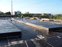
Suspended slab under construction, with the formwork still in place
Suspended slab formwork and rebar in place, ready for concrete pour.

A concrete slab is a common structural element of modern buildings, consisting of a flat, horizontal surface made of cast concrete. Steel-reinforced slabs, typically between 100 and 500 mm thick, are most often used to construct floors and ceilings, while thinner mud slabs may be used for exterior paving ( see below).[1][2]

In many domestic and industrial buildings, a thick concrete slab supported on foundations or directly on the subsoil, is used to construct the ground floor. These slabs are generally classified as ground-bearing or suspended. A slab is ground-bearing if it rests directly on the foundation, otherwise the slab is suspended.[3] For multi-story buildings, there are several common slab designs (

see § Design for more types):

  • Beam and block, also referred to as rib and block, is mostly used in residential and industrial applications. This slab type is made up of pre-stressed beams and hollow blocks and are temporarily propped until set, typically after 21 days.[4]
  • A hollow core slab which is precast and installed on site with a crane
  • In high rise buildings and skyscrapers, thinner, pre-cast concrete slabs are slung between the steel frames to form the floors and ceilings on each level. Cast in-situ slabs are used in high rise buildings and large shopping complexes as well as houses. These in-situ slabs are cast on site using shutters and reinforced steel.

On technical drawings, reinforced concrete slabs are often abbreviated to "r.c.c. slab" or simply "r.c.". Calculations and drawings are often done by structural engineers in CAD software.

Thermal performance

[edit]

Energy efficiency has become a primary concern for the construction of new buildings, and the prevalence of concrete slabs calls for careful consideration of its thermal properties in order to minimise wasted energy.[5] Concrete has similar thermal properties to masonry products, in that it has a relatively high thermal mass and is a good conductor of heat.

In some special cases, the thermal properties of concrete have been employed, for example as a heatsink in nuclear power plants or a thermal buffer in industrial freezers.[6]

Thermal conductivity

[edit]

Thermal conductivity of a concrete slab indicates the rate of heat transfer through the solid mass by conduction, usually in regard to heat transfer to or from the ground. The coefficient of thermal conductivity, k, is proportional to density of the concrete, among other factors.[5] The primary influences on conductivity are moisture content, type of aggregate, type of cement, constituent proportions, and temperature. These various factors complicate the theoretical evaluation of a k-value, since each component has a different conductivity when isolated, and the position and proportion of each components affects the overall conductivity. To simplify this, particles of aggregate may be considered to be suspended in the homogeneous cement. Campbell-Allen and Thorne (1963) derived a formula for the theoretical thermal conductivity of concrete.[6] In practice this formula is rarely applied, but remains relevant for theoretical use. Subsequently, Valore (1980) developed another formula in terms of overall density.[7] However, this study concerned hollow concrete blocks and its results are unverified for concrete slabs.

The actual value of k varies significantly in practice, and is usually between 0.8 and 2.0 W m−1 K−1.[8] This is relatively high when compared to other materials, for example the conductivity of wood may be as low as 0.04 W m−1 K−1. One way of mitigating the effects of thermal conduction is to introduce insulation (

see § Insulation).

Thermal mass

[edit]

The second consideration is the high thermal mass of concrete slabs, which applies similarly to walls and floors, or wherever concrete is used within the thermal envelope. Concrete has a relatively high thermal mass, meaning that it takes a long time to respond to changes in ambient temperature.[9] This is a disadvantage when rooms are heated intermittently and require a quick response, as it takes longer to warm the entire building, including the slab. However, the high thermal mass is an advantage in climates with large daily temperature swings, where the slab acts as a regulator, keeping the building cool by day and warm by night.

Typically concrete slabs perform better than implied by their R-value.[5] The R-value does not consider thermal mass, since it is tested under constant temperature conditions. Thus, when a concrete slab is subjected to fluctuating temperatures, it will respond more slowly to these changes and in many cases increase the efficiency of a building.[5] In reality, there are many factors which contribute to the effect of thermal mass, including the depth and composition of the slab, as well as other properties of the building such as orientation and windows.

Thermal mass is also related to thermal diffusivity, heat capacity and insulation. Concrete has low thermal diffusivity, high heat capacity, and its thermal mass is negatively affected by insulation (e.g. carpet).[5]

Insulation

[edit]

Without insulation, concrete slabs cast directly on the ground can cause a significant amount of extraneous energy transfer by conduction, resulting in either lost heat or unwanted heat. In modern construction, concrete slabs are usually cast above a layer of insulation such as expanded polystyrene, and the slab may contain underfloor heating pipes.[10] However, there are still uses for a slab that is not insulated, for example in outbuildings which are not heated or cooled to room temperature (

see § Mud slabs). In these cases, casting the slab directly onto a substrate of aggregate will maintain the slab near the temperature of the substrate throughout the year, and can prevent both freezing and overheating.

A common type of insulated slab is the beam and block system (mentioned above) which is modified by replacing concrete blocks with expanded polystyrene blocks.[11] This not only allows for better insulation but decreases the weight of slab which has a positive effect on load bearing walls and foundations.

Formwork set for concrete pour.
Concrete poured into formwork. This slab is ground-bearing and reinforced with steel rebar.

Design

[edit]

Ground-bearing slabs

[edit]

Ground-bearing slabs, also known as "on-ground" or "slab-on-grade", are commonly used for ground floors on domestic and some commercial applications. It is an economical and quick construction method for sites that have non-reactive soil and little slope.[12]

For ground-bearing slabs, it is important to design the slab around the type of soil, since some soils such as clay are too dynamic to support a slab consistently across its entire area. This results in cracking and deformation, potentially leading to structural failure of any members attached to the floor, such as wall studs.[12]

Levelling the site before pouring concrete is an important step, as sloping ground will cause the concrete to cure unevenly and will result in differential expansion. In some cases, a naturally sloping site may be levelled simply by removing soil from the uphill site. If a site has a more significant grade, it may be a candidate for the "cut and fill" method, where soil from the higher ground is removed, and the lower ground is built up with fill.[13]

In addition to filling the downhill side, this area of the slab may be supported on concrete piers which extend into the ground. In this case, the fill material is less important structurally as the dead weight of the slab is supported by the piers. However, the fill material is still necessary to support the curing concrete and its reinforcement.

There are two common methods of filling - controlled fill and rolled fill.[13]

  • Controlled fill: Fill material is compacted in several layers by a vibrating plate or roller. Sand fills areas up to around 800 mm deep, and clay may be used to fill areas up to 400 mm deep. However, clay is much more reactive than sand, so it should be used sparingly and carefully. Clay must be moist during compaction to homogenise it.[13]
  • Rolled fill: Fill is repeatedly compacted by an excavator, but this method of compaction is less effective than a vibrator or roller. Thus, the regulations on maximum depth are typically stricter.

Proper curing of ground-bearing concrete is necessary to obtain adequate strength. Since these slabs are inevitably poured on-site (rather than precast as some suspended slabs are), it can be difficult to control conditions to optimize the curing process. This is usually aided by a membrane, either plastic (temporary) or a liquid compound (permanent).[14]

Ground-bearing slabs are usually supplemented with some form of reinforcement, often steel rebar. However, in some cases such as concrete roads, it is acceptable to use an unreinforced slab if it is adequately engineered (

see below).

Suspended slabs

[edit]

For a suspended slab, there are a number of designs to improve the strength-to-weight ratio. In all cases the top surface remains flat, and the underside is modulated:

  • A corrugated slab is designed when the concrete is poured into a corrugated steel tray, more commonly called decking. This steel tray improves strength of the slab, and prevents the slab from bending under its own weight. The corrugations run in one direction only.
  • A ribbed slab gives considerably more strength in one direction. This is achieved with concrete beams bearing load between piers or columns, and thinner, integral ribs in the perpendicular direction. An analogy in carpentry would be a subfloor of bearers and joists. Ribbed slabs have higher load ratings than corrugated or flat slabs, but are inferior to waffle slabs.[15]
  • A waffle slab gives added strength in both directions using a matrix of recessed segments beneath the slab.[16] This is the same principle used in the ground-bearing version, the waffle slab foundation. Waffle slabs are usually deeper than ribbed slabs of equivalent strength, and are heavier hence require stronger foundations. However, they provide increased mechanical strength in two dimensions, a characteristic important for vibration resistance and soil movement.[17]
The exposed underside of a waffle slab used in a multi-storey building

Unreinforced slabs

[edit]

Unreinforced or "plain"[18] slabs are becoming rare and have limited practical applications, with one exception being the mud slab (

see below). They were once common in the US, but the economic value of reinforced ground-bearing slabs has become more appealing for many engineers.[10] Without reinforcement, the entire load on these slabs is supported by the strength of the concrete, which becomes a vital factor. As a result, any stress induced by a load, static or dynamic, must be within the limit of the concrete's flexural strength to prevent cracking.[19] Since unreinforced concrete is relatively very weak in tension, it is important to consider the effects of tensile stress caused by reactive soil, wind uplift, thermal expansion, and cracking.[20] One of the most common applications for unreinforced slabs is in concrete roads.

Mud slabs

[edit]

Mud slabs, also known as rat slabs, are thinner than the more common suspended or ground-bearing slabs (usually 50 to 150 mm), and usually contain no reinforcement.[21] This makes them economical and easy to install for temporary or low-usage purposes such as subfloors, crawlspaces, pathways, paving, and levelling surfaces.[22] In general, they may be used for any application which requires a flat, clean surface. This includes use as a base or "sub-slab" for a larger structural slab. On uneven or steep surfaces, this preparatory measure is necessary to provide a flat surface on which to install rebar and waterproofing membranes.[10] In this application, a mud slab also prevents the plastic bar chairs from sinking into soft topsoil which can cause spalling due to incomplete coverage of the steel. Sometimes a mud slab may be a substitute for coarse aggregate. Mud slabs typically have a moderately rough surface, finished with a float.[10]

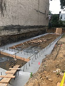
Substrate and rebar prepared for pouring a mud slab

Axes of support

[edit]

One-way slabs

[edit]

A one-way slab has moment-resisting reinforcement only in its short axis, and is used when the moment in the long axis is negligible.[23] Such designs include corrugated slabs and ribbed slabs. Non-reinforced slabs may also be considered one-way if they are supported on only two opposite sides (i.e. they are supported in one axis). A one-way reinforced slab may be stronger than a two-way non-reinforced slab, depending on the type of load.

The calculation of reinforcement requirements for a one-way slab can be extremely tedious and time-consuming, and one can never be completely certain of the best design.[citation needed] Even minor changes to the project can necessitate recalculation of the reinforcement requirements. There are many factors to consider during the structural structure design of one-way slabs, including:

  • Load calculations
  • Bending moment calculation
  • Acceptable depth of flexure and deflection
  • Type and distribution of reinforcing steel

Two-way slabs

[edit]

A two-way slab has moment resisting reinforcement in both directions.[24] This may be implemented due to application requirements such as heavy loading, vibration resistance, clearance below the slab, or other factors. However, an important characteristic governing the requirement of a two-way slab is the ratio of the two horizontal lengths. If where is the short dimension and is the long dimension, then moment in both directions should be considered in design.[25] In other words, if the axial ratio is greater than two, a two-way slab is required.

A non-reinforced slab is two-way if it is supported in both horizontal axes.

Construction

[edit]

A concrete slab may be prefabricated (precast), or constructed on site.

Prefabricated

[edit]

Prefabricated concrete slabs are built in a factory and transported to the site, ready to be lowered into place between steel or concrete beams. They may be pre-stressed (in the factory), post-stressed (on site), or unstressed.[10] It is vital that the wall supporting structure is built to the correct dimensions, or the slabs may not fit.

On-site

[edit]

On-site concrete slabs are built on the building site using formwork, a type of boxing into which the wet concrete is poured. If the slab is to be reinforced, the rebars, or metal bars, are positioned within the formwork before the concrete is poured in.[26] Plastic-tipped metal or plastic bar chairs, are used to hold the rebar away from the bottom and sides of the form-work, so that when the concrete sets it completely envelops the reinforcement. This concept is known as concrete cover. For a ground-bearing slab, the formwork may consist only of side walls pushed into the ground. For a suspended slab, the formwork is shaped like a tray, often supported by a temporary scaffold until the concrete sets.

The formwork is commonly built from wooden planks and boards, plastic, or steel. On commercial building sites, plastic and steel are gaining popularity as they save labour.[27] On low-budget or small-scale jobs, for instance when laying a concrete garden path, wooden planks are very common. After the concrete has set the wood may be removed.

Formwork can also be permanent, and remain in situ post concrete pour. For large slabs or paths that are poured in sections, this permanent formwork can then also act as isolation joints within concrete slabs to reduce the potential for cracking due to concrete expansion or movement.

In some cases formwork is not necessary. For instance, a ground slab surrounded by dense soil, brick or block foundation walls, where the walls act as the sides of the tray and hardcore (rubble) acts as the base.

See also

[edit]
  • Shallow foundation (Commonly used for ground-bearing slabs)
  • Hollow-core slab (Voided slab, one-way spanning)
  • Beam and block (voided slab, one way spanning)
  • Voided biaxial slab (Voided slab, two-way spanning)
  • Formwork
  • Precast concrete
  • Reinforced concrete
  • Rebar
  • Concrete cover

References

[edit]
  1. ^ Garber, G. Design and Construction of Concrete Floors. 2nd ed. Amsterdam: Butterworth-Heinemann, 2006. 47. Print.
  2. ^ Duncan, Chester I. Soils and Foundations for Architects and Engineers. New York: Van Nostrand Reinhold, 1992. 299. Print.
  3. ^ "Ground slabs - Introduction". www.dlsweb.rmit.edu.au. Archived from the original on 2019-11-18. Retrieved 2017-12-07.
  4. ^ "What is a rib and block slab?". www.royalconcreteslabs.co.za. Royal concrete slabs.
  5. ^ a b c d e Cavanaugh, Kevin; et al. (2002). Guide to Thermal Properties of Concrete and Masonry Systems: Reported by ACI Committee 122. American Concrete Institute.
  6. ^ a b Campbell-Allen, D.; Thorne, C.P. (March 1963). "The thermal conductivity of concrete". Magazine of Concrete Research. 15 (43): 39–48. doi:10.1680/macr.1963.15.43.39. UDC 691.32.001:536.21:691.322.
  7. ^ Valore, R.C. Jr. (February 1980). "Calculation of U-values of Hollow Concrete Masonry". Concrete International. 2: 40–63.
  8. ^ Young, Hugh D. (1992). "Table 15.5". University Physics (7th ed.). Addison Wesley. ISBN 0201529815.
  9. ^ Sabnis, Gajanan M.; Juhl, William (2016). "Chapter 4: Sustainability through Thermal Mass of Concrete". Green Building with Concrete: Sustainable Design and Construction (2nd ed.). Taylor & Francis Group. ISBN 978-1-4987-0411-3.
  10. ^ a b c d e Garber, George (2006). Design and Construction of Concrete Floors (2nd ed.). Amsterdam: Butterworth-Heinemann. ISBN 978-0-7506-6656-5.
  11. ^ "What is a polystyrene concrete slab?". www.royalconcreteslabs.co.za. Royal concrete slabs.
  12. ^ a b McKinney, Arthur W.; et al. (2006). Design of Slabs-on-Ground: Reported by ACI Committee 360 (PDF). American Concrete Institute. Archived from the original (PDF) on 2021-05-08. Retrieved 2019-04-04.
  13. ^ a b c Staines, Allan (2014). The Australian House Building Manual. Pinedale Press. pp. 40–41. ISBN 978-1-875217-07-6.
  14. ^ "Concrete in Practice 11 - Curing In-Place Concrete" (PDF). Engineering.com. National Ready Mixed Concrete Association. Archived from the original (PDF) on 4 April 2019. Retrieved 4 April 2019.
  15. ^ "Ribbed Slabs Datasheet" (PDF). Kaset Kalip. Archived from the original (PDF) on 29 March 2018. Retrieved 4 April 2019.
  16. ^ "Ribbed and waffle slabs". www.concretecentre.com. Retrieved 2019-04-04.
  17. ^ Concrete Framed Buildings: A Guide to Design and Construction. MPA The Concrete Centre. 2016. ISBN 978-1-904818-40-3.
  18. ^ Garrison, Tim (19 February 2014). "Clearing the confusion on 'plain concrete'". Civil & Structural Engineer. Archived from the original on 8 May 2019. Retrieved 8 May 2019.
  19. ^ Walker, Wayne. "Reinforcement for slabs on ground". Concrete Construction. Retrieved 8 May 2019.
  20. ^ "Rupture depth of an unreinforced concrete slab on grade" (PDF). Aluminium Association of Florida, Inc. Archived from the original (PDF) on 2020-09-26. Retrieved 2019-05-08.
  21. ^ Arcoma, Peter. "What is a mud slab?". Builder-Questions.com. Retrieved 8 May 2019.
  22. ^ Postma, Mark; et al. "Floor Slabs". Whole Building Design Guide. National Institute of Building Sciences. Retrieved 8 May 2019.
  23. ^ Gilbert, R. I. (1980). UNICIV Report 211 (PDF). University of New South Wales.
  24. ^ Prieto-Portar, L. A. (2008). EGN-5439 The Design of Tall Buildings; Lecture #14: The Design of Reinforced Concrete Slabs (PDF). Archived from the original (PDF) on 2017-08-29. Retrieved 2019-04-04.
  25. ^ "What is the difference between one way and two way slab?". Basic Civil Engineering. 16 June 2019. Retrieved 8 July 2019.
  26. ^ Concrete Basics: A Guide to Concrete Practice (6th ed.). Cement Concrete & Aggregates Australia. 2004. p. 53.
  27. ^ Nemati, Kamran M. (2005). "Temporary Structures: Formwork for Concrete" (PDF). Tokyo Institute of Technology. Archived from the original (PDF) on 12 July 2018. Retrieved 4 April 2019.
[edit]
  • Concrete Basics: A Guide to Concrete Practice
  • Super Insulated Slab Foundations
  • Design of Slabs on Ground Archived 2021-05-08 at the Wayback Machine


Photo
Photo
Photo
Photo

Reviews for


Jeffery James

(5)

Very happy with my experience. They were prompt and followed through, and very helpful in fixing the crack in my foundation.

Sarah McNeily

(5)

USS was excellent. They are honest, straightforward, trustworthy, and conscientious. They thoughtfully removed the flowers and flower bulbs to dig where they needed in the yard, replanted said flowers and spread the extra dirt to fill in an area of the yard. We've had other services from different companies and our yard was really a mess after. They kept the job site meticulously clean. The crew was on time and friendly. I'd recommend them any day! Thanks to Jessie and crew.

Jim de Leon

(5)

It was a pleasure to work with Rick and his crew. From the beginning, Rick listened to my concerns and what I wished to accomplish. Out of the 6 contractors that quoted the project, Rick seemed the MOST willing to accommodate my wishes. His pricing was definitely more than fair as well. I had 10 push piers installed to stabilize and lift an addition of my house. The project commenced at the date that Rick had disclosed initially and it was completed within the same time period expected (based on Rick's original assessment). The crew was well informed, courteous, and hard working. They were not loud (even while equipment was being utilized) and were well spoken. My neighbors were very impressed on how polite they were when they entered / exited my property (saying hello or good morning each day when they crossed paths). You can tell they care about the customer concerns. They ensured that the property would be put back as clean as possible by placing MANY sheets of plywood down prior to excavating. They compacted the dirt back in the holes extremely well to avoid large stock piles of soils. All the while, the main office was calling me to discuss updates and expectations of completion. They provided waivers of lien, certificates of insurance, properly acquired permits, and JULIE locates. From a construction background, I can tell you that I did not see any flaws in the way they operated and this an extremely professional company. The pictures attached show the push piers added to the foundation (pictures 1, 2 & 3), the amount of excavation (picture 4), and the restoration after dirt was placed back in the pits and compacted (pictures 5, 6 & 7). Please notice that they also sealed two large cracks and steel plated these cracks from expanding further (which you can see under my sliding glass door). I, as well as my wife, are extremely happy that we chose United Structural Systems for our contractor. I would happily tell any of my friends and family to use this contractor should the opportunity arise!

Chris Abplanalp

(5)

USS did an amazing job on my underpinning on my house, they were also very courteous to the proximity of my property line next to my neighbor. They kept things in order with all the dirt/mud they had to excavate. They were done exactly in the timeframe they indicated, and the contract was very details oriented with drawings of what would be done. Only thing that would have been nice, is they left my concrete a little muddy with boot prints but again, all-in-all a great job

Dave Kari

(5)

What a fantastic experience! Owner Rick Thomas is a trustworthy professional. Nick and the crew are hard working, knowledgeable and experienced. I interviewed every company in the area, big and small. A homeowner never wants to hear that they have foundation issues. Out of every company, I trusted USS the most, and it paid off in the end. Highly recommend.

View GBP